Appropriate Handling
The correct
rope inspection
Why rope inspection?
Ropes in rope drives are open gears which are exposed to external influences but also have common signs of wear. Above all however, the service life of a rope is limited. Once the rope has reached its discard criterion, it has also reached the end of its service life. The rope’s discard state must be detected early enough to avoid accidents such as a rope break. This detection requires regular rope inspections, which document the percentage of rope life left before it is ready to be discarded.
A meaningful rope inspection should consider the following points:
- General visual inspection (places requiring increased attention)
- Diameter measurement with a suitable tool and at different strategic posititons
- Measurement of rope lay length
- Evaluation of degree of corrosion, if any
- Inspection and classification of the most frequently stressed rope zone for wire breaks
- Measurement of the the groove diameters located in the rope drive
- Evaluation of the amount of lubricant on the rope surface.
Such inspections must be carried out on a regular basis. The intervals of the different tasks mentioned above may vary. A visual inspection should be carried out daily, but the diameter for example should be measured monthly or quarterly, depending on the load and frequency of use.

General visual inspection / daily visual inspection
With a general visual inspection, obvious damage such as cracked strands or errors in the reeving should be detected at an early stage and, if possible, repaired before the start of operation.
In this case, places near the end connection or places that could get into contact with the crane must be inspected with increased attention. This inspection should be carried out carefully by the crane operator.
Regular inspection
The regular inspection must be carried out by a competent person. The complete crane system should be monitored and maintained.
Practical examples
- Measurements to be carried out on a quarterly basis: Diameter and lay length
- Annual measurements: groove size, sheave depth, hardness of sheaves and drum (optional)
Tools required for the rope inspection
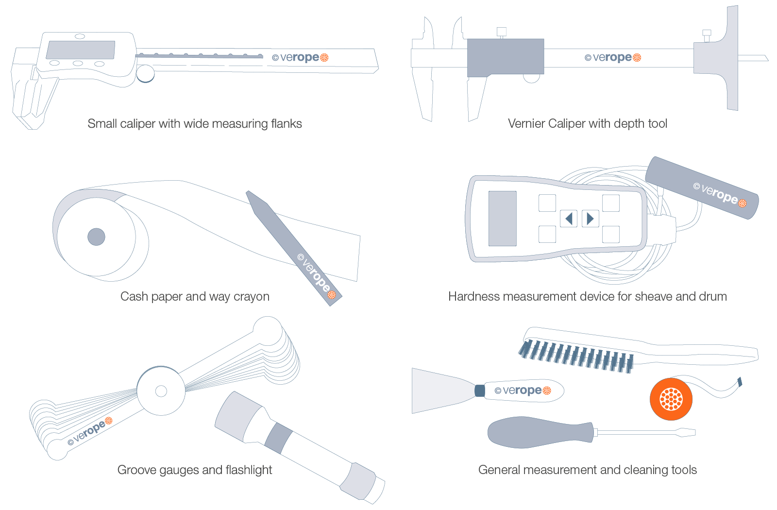
Measuring the diameter of the rope
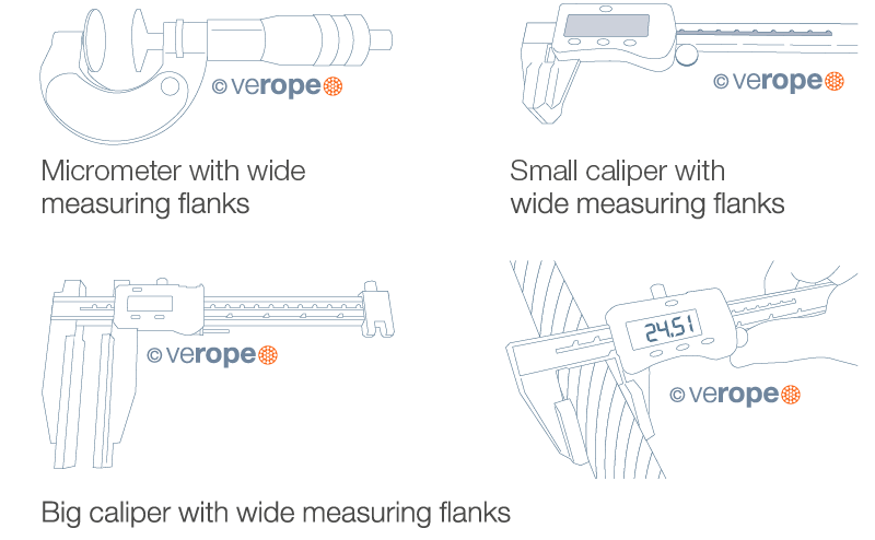
Measuring the diameter of a wire rope during operation provides information on the wear and the diameter reduction. However, an increased diameter may also occur to a structural change. The diameter of the rope should always be determined with the aid of suitable measurement equipment. Small calipers with wider measurement flanks are advantageous here. The following pictures display suitable measuring equipment.
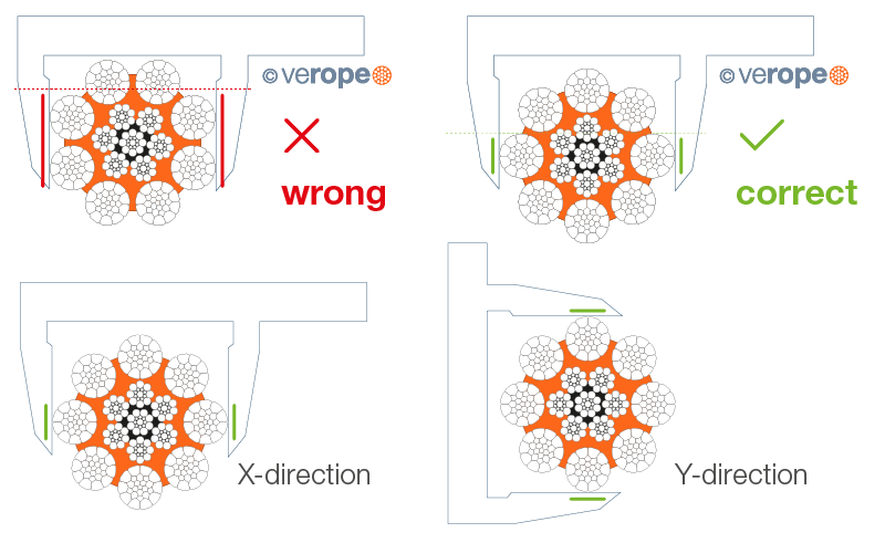
A rope must always be measured at its widest point, i.e. from strand crown to strand crown. A complete measurement consists of two measurements in the X-direction and two measurements in the Y-direction, each approximately 1 m apart. The resulting average of the values describes the current rope diameter.
How to measure the lay length of a rope
An indication of whether a rope has been twisted by force or has generally undergone an unnatural twist can be found in a resulting change of lay length. In order to measure the lay length, the following utensils are required. A negative of the rope surface is created with the help of a cash register roller and a wax crayon. In this process, a cash register paper must be placed on the rope surface while a wax crayon is moved across with downwards pressure. As a result, there is an impression of the rope strands on the paper.
In order to determine the lay length of the rope a certain number of impressions must be counted. Here the number of outer strands is decisive (in the picture above there are 8 outer strands). The distance from the beginning and end point gives the lay length in mm. It is recommended to count at least three measurements and divide the total length by three parts in order to reduce measuring errors (see picture).

Length divided by amount of measurements
Messen von Seilrollenprofilen
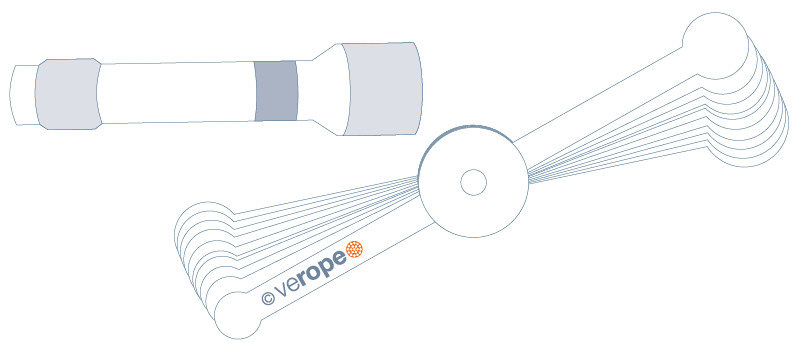
A rope inspection includes not only the inspection of the rope itself, but also of the sheaves in which the rope runs. Special measuring equipment is required to measure the groove diameter: Groove gauges and a flashlight.
Such groove gauges are available upon request from verope®. The values indicated on the gauge are actual values and not, as is sometimes the case, target values. The flashlight serves as an aid to determine the exact measurement. Here the gauge in the groove is illuminated from behind. If light shines through on the sides between the gauge and the sheave, this indicates, that the used gauge is too large. If there is no light visible at the complete radius of the gauge, the correct groove size corresponds to the gauge size used.
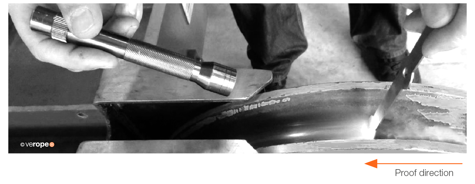
The following pictures show the different scenarios that can occur during measurement.
R = Rillenradius
d = Seilnenndurchmesser

The complete groove gauge has the dimension of the groove bottom, no light is showing indicating the correct gauge size.

The light is clearly visible between the bottom of the gauge and the sheave groove: The groove gauge used is too large.

The light slot is not covered by the complete radius: Gauge is too small
According to the standard, the groove radius R should be between 0.525 x d and 0.550 x d, the optimum groove radius is 0.5375 x d.
Example:
For a rope with a nominal diameter of 22 mm, the following values apply:
- Minimum allowed groove diameter: 23.10 mm
- Optimum groove diameter: 23.66 mm
- Maximum allowed groove diameter: 24.20 mm
The following diagram shows the effect on rope service life with different groove size ratios.
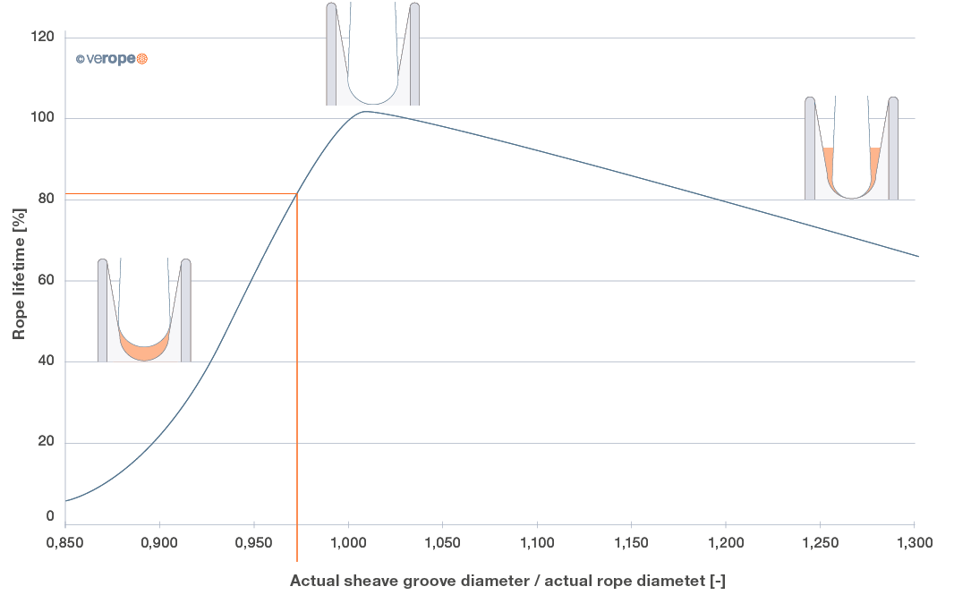
Example:
Rope with an actual diameter of 22,66 mm working in a groove with an actual diameter of 22 mm experiences a service life loss of approx. 20%.

Groove depth
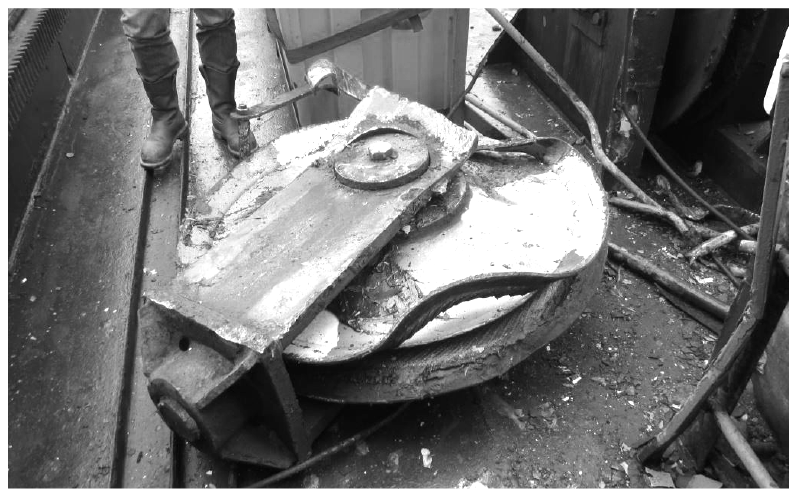
According to ISO 16625, the groove depth should be no greater than 1.5 times the rope diameter and in addition, the bottom of the groove must be circular. The maximum permissible depth until the sheave has to be replaced due to wear must be specified by or obtained from the sheave manufacturer. This value must be observed at all times as disregarding it can result in serious accidents as a result of material failure.
Material Hardness
Ropes usually have different strengths, tensile grades such as 1770 N/mm2, 1960 N/mm2 or 2160 N/mm2 are common. The diagram to the right shows the respective degree of hardness in HV (Vickers Hardness) for the corresponding strength class. The hardness of the sheaves and drum should be between 300 – 350 HV. This is due to the fact that rope sheaves that are too soft absorb the pure wear of the system and thus the discard criterion of the rope is more difficult to detect. If the used rope sheave or rope drum has a higher hardness value, this does no harm to the system, but involves higher hardening costs.
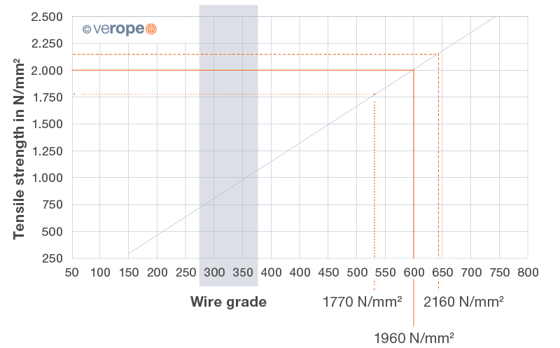
Wire breaks on the rope surface
Wire breaks on the rope surface are caused by bending stress on the rope when running over sheaves. The number of wire breaks over a defined length must
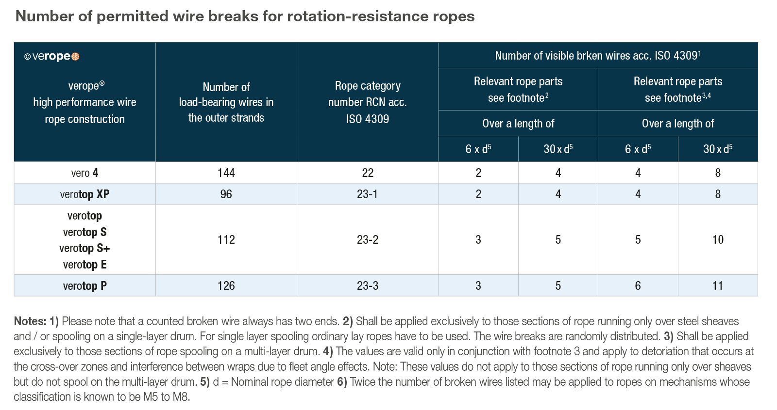
The number of wire breaks over a defined length must not exceed a certain number corresponding to its design and subsequently to the RCN (Rope Category Number), otherwise it must be discarded immediately.
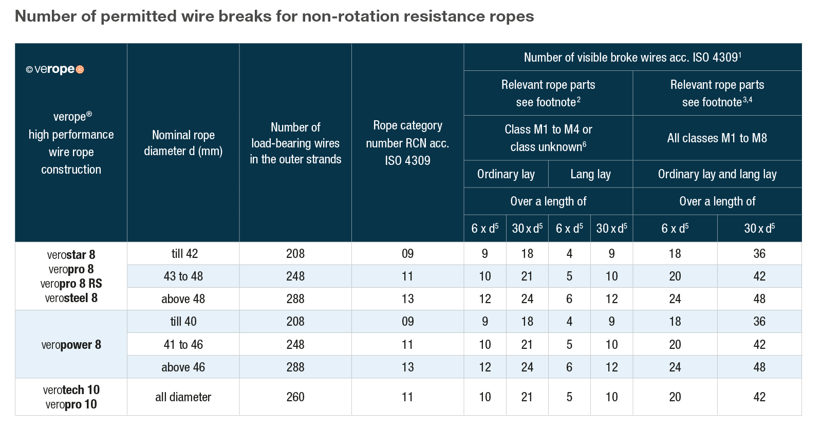
Whereas the distribution of wire breaks does not seem to follow a certain pattern, the shown standard cannot be applied to wire breaks caused by contact with the steel structure.
Removal of protruding wires
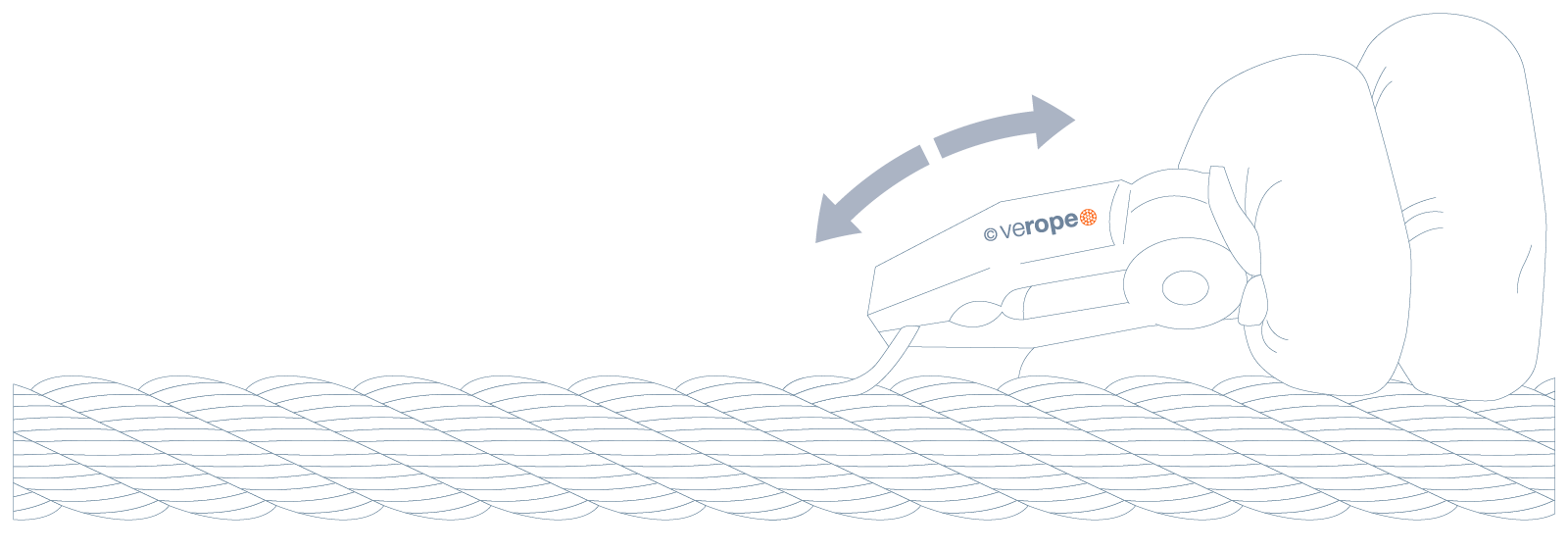
Some wire breaks may cause the wire to protrude from the rope. This wire can damage neighboring wires when it runs over the sheave again causing secondary wire breaks. With the help of pliers and continuous back and forth bending of the protruding wire, it can be removed and is no longer a danger to neighboring wires.
External Corrosion
Ropes in particular environments or with a high lifetime start to corrode. The standard distinguishes different corroding levels.
The following pictures shows the different levels according to ISO 4309.
Guideline to rate the intensity of the corrosion
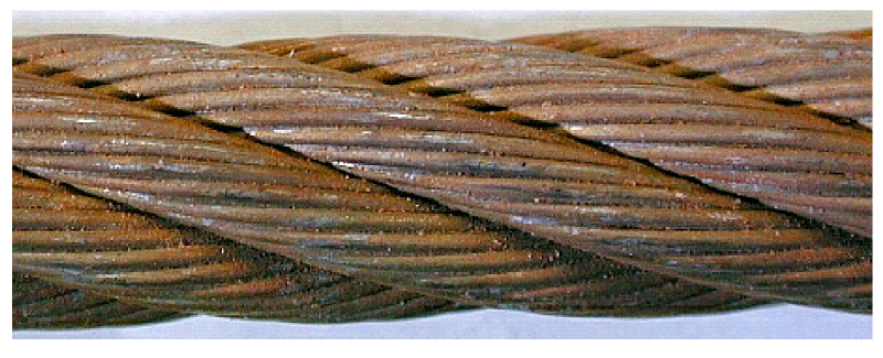
1. Beginning of surface oxidation, can be wiped clean, superficial – Rating: 0% towards discard
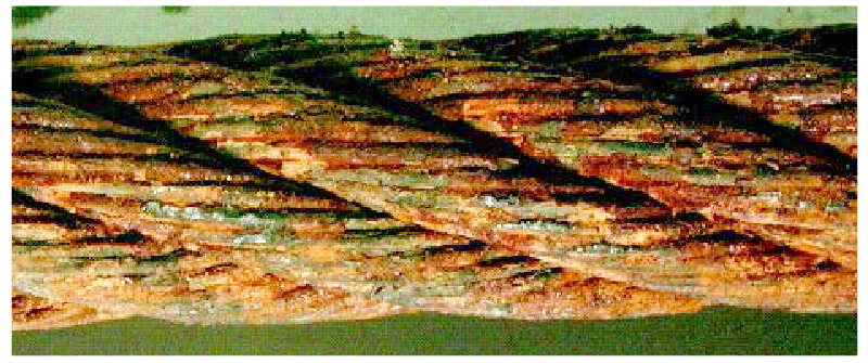
3. Surface of wire now greatly affected by oxidation – Rating: 60% towards discard
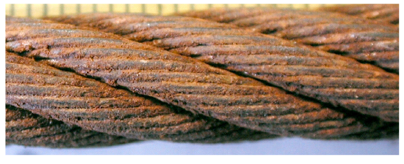
2. Wires rough to touch, general surface oxidation – Rating: 20% towards discard
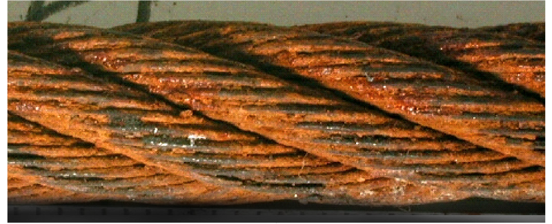
4. Surface heavily pitted and wires quite slack, gaps between wires – Discard immediatly
Diameter reduction
The rope diameter of a working rope is constantly reduced over its entire service life.
This reduction of the diameter is caused by abrasion and wear and is evaluated according to the following table and classified up to the point of discard maturity.
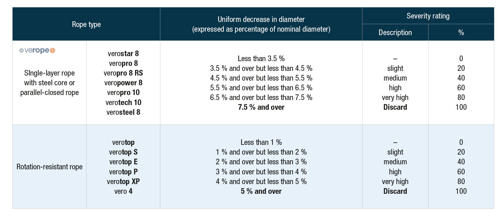
The following formula is used to determine the diameter reduction.

Example:
A single layer steel core rope with a nominal diameter of 22.00 mm has a reference diameter of 22.80 mm as in calculation example and a measured diameter of 21.90 mm.
To proof:

The rope has reached a discard maturity of 20 % by means of diameter reduction
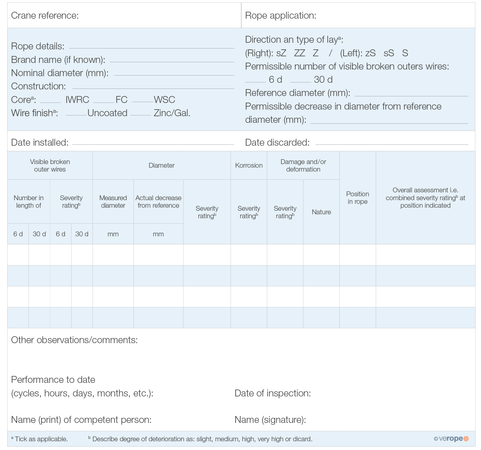
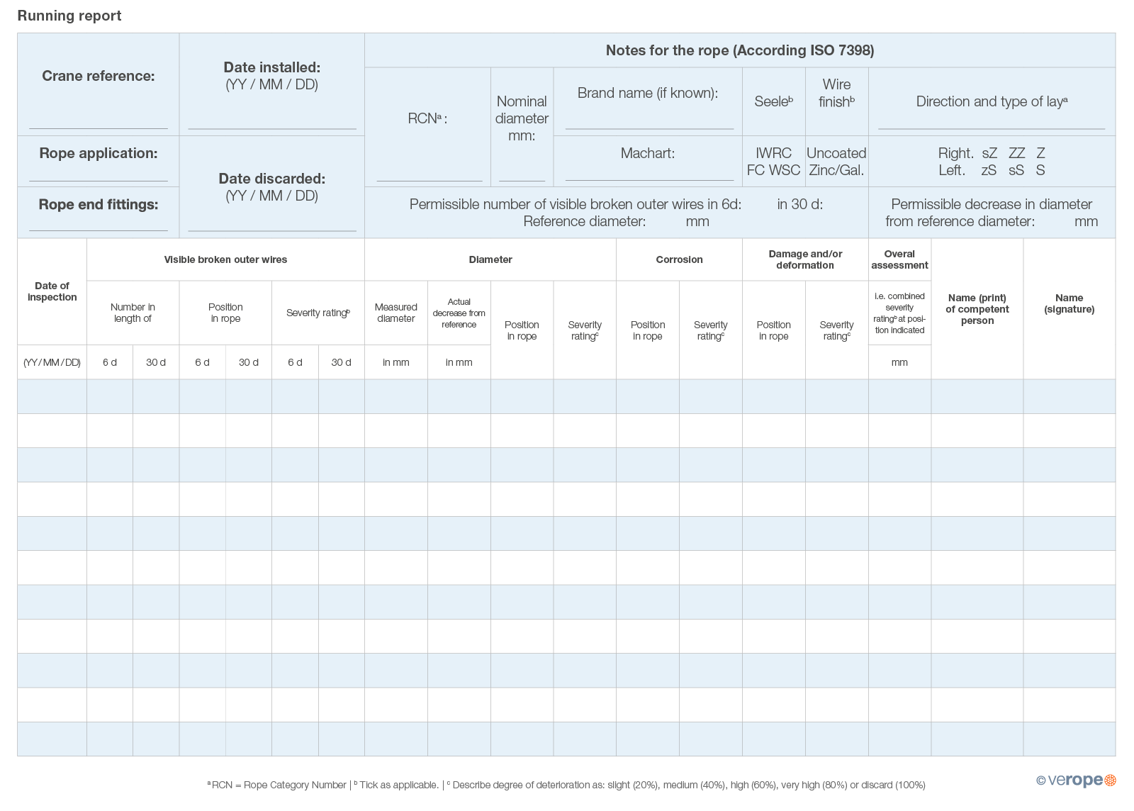
Inspection report
The inspection report of DIN ISO 4309 provides helpful support. This report lists all relevant points of a structured rope inspection.

With the following hints we would like to draw your attention to some essential points for correct selection, operation and maintenance of wire ropes. In addition to technical literature on wire ropes, national and international standards, the verope® team will be happy to assist you with all questions concerning wire ropes. Please contact us!
The following points refer to the information that complies with the indications in this article. Here you will find an overview of all important information.

No. 4:
Wire ropes and their end fittings are not fatigue resistant endlessly and must therefore be controlled periodically for safe operation. Wire ropes and the end fittings must be discarded before reaching a unsafe condition. Note please refer to the respective valid international or national standards (e.g. ISO 4309, EN 12385 and EN 13411) and the technical literature for expert inspection as well as for the correct determination of the discard maturity of wire ropes and their end fittings. During installation of ropes which are provided with an end fitting it must be ensured that these have been carried out in accordance with the operating instructions at the designated place and can be installed in the correct position. For end fittings, which can be dismantled, e.g. wedge end clamps, it is absolutely necessary to remove the rope or end fitting according to manufacturer specifications. For questions, ambiguities or problems, please contact the customer service of the verope® technical department: TCS @ verope.com

No. 13:
The intervals between periodic inspections are dependending on the condition, the intensity and the external influences of the application.
If you have any questions, ambiguities or problems, please contact verope® Technical Customer Service: TCS@verope.com
Protect yourself and others!
Rope failure can cause serious material damage, injury or death!