Rope technology
All about
the rope
➜ Wire rope diameter
A distinction is made between the nominal rope diameter and the effective rope diameter. The nominal wire rope diameter is an agreed theoretical value for the diameter of the smallest circle circumscribing the outer strands.
The effective rope diameter, also called actual rope diameter, is the diameter of the smallest circle enclosing all outer strands, as measured on the rope itself. The tolerance range for the effective rope diameter is specified in related national and international standards. According to EN 12385-4 it is between -0% and +5% (for nominal rope diameters ≥ 8mm)
This means that the effective rope diameter upon delivery must neither be smaller nor bigger than 5% than the nominal rope diameter. The tolerance range is often higher for smaller ropes like 3mm to 7mm nominal diameter. In the Oil and Gas industry, which is firmly based on US regulations, a tolerance range from -1% to 4% is applied. The effective rope diameter changes depending on the load applied. Therefore the effective rope diameter should in critical cases be measured on a rope that is loaded with 5% of the calculated breaking strength. verope® produces standard tolerances of +2% to +4% and special tolerances upon request.
➜ Wire rope diameter
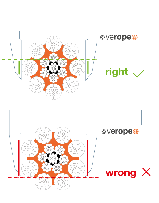
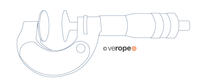
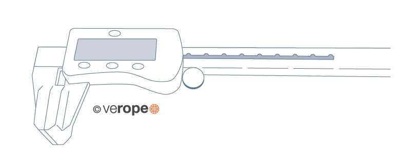
In order to define the correct effective rope diameter, the correct measuring device has to be used. The measurement should strictly be done over the round ends (circumscribed circle of the rope). If one measures in the strand valleys, the result will be inacurate. For ropes with an uneven number of outer strands, it is important that the measuring surface covers several strands (figure 10).
➜ Types of measuring devices

➜ Lay direction of a wire rope
A distinction is made between right hand and left hand lay ropes.
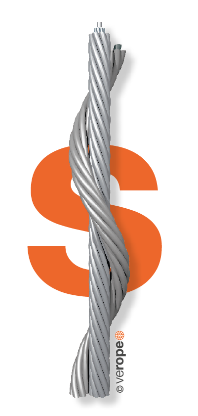
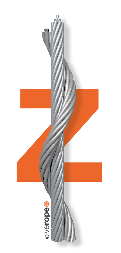
The lay direction is left hand, when the strands (moving away from the beholder) are rotated counterclockwise (figure 14). The lay direction of a rope is right hand, when its strands (moving away from the beholder) are rotated clockwise (figure 15).
The lay direction of a rope is often given by a capital S for the left hand lay rope and by a capital Z for the right hand lay rope. Others often use RH for Right Hand and LH for Left Hand lay ropes.
➜ Rope design
By the design of a wire rope, one understands the formation principle according to which the elements of the wire rope (the wires and the strands) are relatively arranged to each other. The designation of a fiber core is FC, for an independent steel wire rope core it is IWRC.
As an example all round strand ropes of the 6×19 Warrington design with a fiber core have the construction 6 x [1-6-(6-6)] – FC.
➜ Fill factor of a rope
The fill factor of a rope is defined as the ratio of the metallic cross section of the rope (or a simplified calculation of the sum of the single wire cross sections) related to the nominal rope diameter. The fill factor specifies which amount of space the wires and strands take in the rope (figure 16).
The fill factors of the most common ropes are between 0,46 and 0,75. This means, that the amount of steel in the rope volume is about 46% to 75%. Wire ropes with a wire rope core have higher fill factors than ropes with a fiber core.
A rope of the design 6×25 Filler-FC for example has a fill factor of 0,50 and a rope with a design 6×25 Filler-IWRC has a fill factor of 0,58.
Usually fill factors of wire ropes with a fibre core (FC) decrease with an increasing number of outer strands. A rope of the design 6×25 Filler-FC has a fill factor of 0,50, a rope of the design 8×25 Filler-FC has only a fill factor of 0,445.
Usually fill factors of wire ropes with a wire rope core increase with an increasing number of outer strands. A rope of the design 6×25 Filler-IWRC has a fill factor of 0,58 and a rope of the design 8×25 Filler-IWRC has a fill factor of 0,587.
Wire ropes that are made of compacted strands have higher fill factors than ropes of uncompacted strands. By compacting and rotary swaging of the rope itself the fill factor can further be increased.

figure 16: The fill factor of the strand is the proportion of the metallic cross sections (white surfaces) at the metall cross section area of the minimum circumscribed circle (white and grey surfaces).
➜ Lay types of wire ropes
Two lay types are to be considered: Regular or ordinary lay and lang’s lay. In regular lay ropes the lay direction of the wires in the strands is opposite to the lay direction of the strands in the rope. We distinguish between regular lay left hand (right hand strand, left hand rope, zS) (figure 17) and regular lay right hand (left hand strand, right hand rope, sZ) (figure 18).
In lang’s lay ropes the lay direction of the wires in the strands is equal to the strands in the rope. We distinguish between lang’s lay left hand (left hand strand, left hand rope, sS) (figure 19) and lang’s lay right hand (right hand strand, right hand rope, zZ) (figure 20).
The advantages of regular lay ropes are:
• Better structural stability
• Higher number of broken wires are allowed
• Easier identification of broken wires
The advantages of lang’s lay ropes are:
• Better contact in the groove of the sheaves
• Superior resistance to wear
• Longer lifetime in case of high dead loads
• Considerably better spooling behavior on a multi-layer drum
