Rope Technology
Crane components
Drums
Drums are used to pull in and store steel wire ropes. The rope can be spooled in single-layer or in multi-layer spooling.
Single-layer drums can be ungrooved or have a helical groove. The pitch of the drum will typically be nominal rope diameter + 10 %.
Multi-layer drums can be helical or have a Lebus®-type groove. While helical-type grooves have a constant pitch of the drum, the Lebus®-type grooves show on 1/3 of the circumference of the drum a pitch of 0° (means they are parallel to the flange), followed by drum grooves which are inclined by 3° on about 1/6 of the circumference of the drum. The Lebus®-type grooves typically have a pitch of about nominal rope diameter plus 4% or to plus 5 %.

The flexibility and the radial stability of a steel wire rope and the D/d ratio of the drum are important influences for the quality of the spooling.
In order to avoid twisting of the wire rope by the drum, the drum rule should be obeyed. A right hand drum should be operated with a left hand lay rope, a left hand drum should be operated with a right hand lay rope.
In multi-layer drums, the direction of the drum changes with every layer. Here the direction of the lay of the steel wire rope should either be chosen to suit the direction of the reeving (a left hand reeving should have a right hand rope and a right hand reeving should have a left hand rope) or the lay direction of the steel wire rope should be chosen for the most used layer of the drum (see also page 52 & 53).
Sheaves
Sheaves are used to change the direction of a steel wire rope. When entering a sheave, a steel wire rope will be bent and subjected to half a bending cycle. When leaving the sheave on the other side, the rope section will be straightened and thereby be subjected to another half a bending cycle.
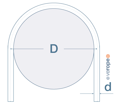
The diameter of a sheave is often measured as a multiple of a rope diameter, the D/d ratio. A D/d ratio of 20 means that the sheave diameter (measured from center rope to center rope, see figure 73) is 20 times the nominal rope diameter. The tread diameter here is 19 x d.
The fatigue life of a steel wire rope will increase with increasing D/d ratio (see figure 53, page 32).

ISO 16625 allows groove angles between 30° and 60° (figure 72). DIN15061 requires groove angles of minimum 45°, British Standard 6570 specified groove angles of 52°.
If a rope travels over a sheave under a fleet angle, it will roll down the flanges and get twisted. Tests have shown that the amount of twist brought into the rope is a function of the groove angle: The larger the groove angle, the less twisting will occur.
A steel wire rope diameter can measure up to nominal rope diameter + 5 %. In order to accommodate a steel wire rope, according to ISO 16625 the groove diameter should therefore measure between nominal rope diameter +5 % to + 10 %, in the ideal case +6 %.

verope® offers groove gauges to measure the actual groove diameter (figure 74).